Welcome to the Tips & Tricks: Troubleshooting Traces page. Follow these tips to help you use tools more efficiently and gain a better understanding of the products. Use them! Share them!
One of the biggest benefits of a GIS is its ability to analyze a network, and one of the easiest forms of network analysis is a network trace. Whether you want to know how many transformers are between a customer and the circuit breaker, or how small an area you can isolate during repairs, ArcFM network traces can provide the answer. But what if your trace isn't returning the kind of results you expected, or any results at all? Check out these tips for getting your trace results back on track.
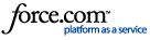
Tip 1: Set the traceable network on the Utility Network Analyst toolbar.
Although a GIS editor can edit features in any network at any time, only one network's features are traceable at a time. To change the traceable network, from the Customize menu choose Toolbars > Utility Network Analyst. Once the Utility Network Analyst toolbar opens, make sure the first drop-down is set to the network you want to trace.
If your ArcFM Electric/Gas/Water trace buttons are grayed out, this Utility Network Analyst is the most likely culprit. This setting also affects any tools that run traces as part of their operation, such as Phase Swap.
Tip 2: Remove any barriers between the trace start point and the source feature.
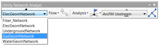
If your network makes use of sources (all electric networks, and some gas and water networks), then the electricity/gas/water originates at the source feature, flows outward in all directions including toward your trace start point (wherever you placed the green box "flag") and beyond to other features, only stopping when it runs out of features or reaches an obstacle, such as a closed valve or an open switch. The Utility Network Analyst toolbar offers barriers that you can place on network branches that aren't currently of interest to you.
Click the Add Edge Barrier tool, then on the map click on a line in the network to place a barrier.
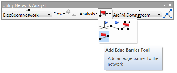
By decreasing the number of features that must be analyzed in the trace, you can get your trace results sooner.
Two edge barriers (each symbolized by a small red X) prevent the trace from following branches that are currently not of interest to us.
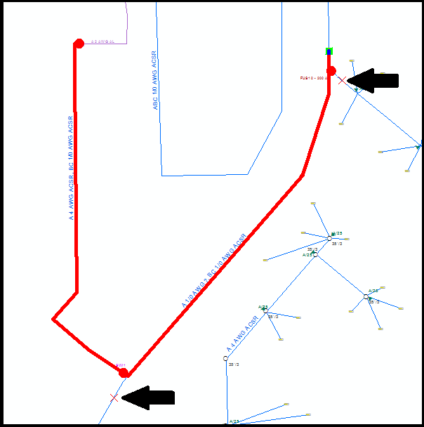
However, if there is a barrier between the source feature and your trace start point, then everything beyond the barrier - including your trace start point - will not be analyzed, and so your trace will return no results.
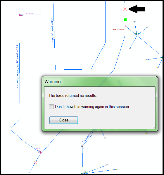
The new barrier between the trace starting point (green box) and the source prevents the trace from finding any results.
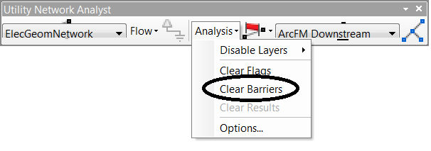
To remove the barriers, from the Utility Network Analyst toolbar choose Analysis > Clear Barriers. Alternatively, on the ArcFM Electric/Gas/Water Traces toolbar you can click Clear Flags, Barriers, and Results.
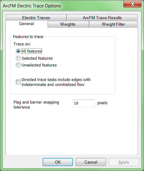
Tip 3: Make sure you are tracing all features, not just the selected set.
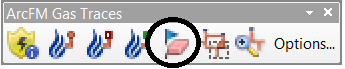
If your selected includes the source feature, your trace start point, and all the features between them, then tracing just within the selected set would work and could save time over tracing all connected features. However, if your selected set does not include all the necessary features then the trace will not be able to run successfully. To see whether you are tracing all features or just within the selected set, on any ArcFM tracing toolbar click Options, then view the General tab.
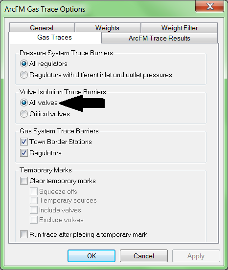
Tip 4: For gas and water networks only: Make sure trace is stopping at all valves, not just critical valves.
Some gas and water utilities plan their networks so that each area has a known "critical" valve that can be closed to isolate the whole area from the rest of the network. In an emergency the critical valve would be closed immediately and then the utility would take time to determine the exact location of the problem and which non-critical valves could be closed to isolate a smaller set of features. If your GIS includes valves that have been marked as critical, you can run the isolation trace looking only for critical valves, or fine-tune the results by looking at non-critical valves, too. If your GIS does not include valves that have been marked as critical, then asking your isolation trace to look only for critical valves is not going to get you useful results. To adjust this setting, on the ArcFM Gas (or Water) Traces toolbar click Options, then on the Gas (or Water) Traces tab choose All Valves.
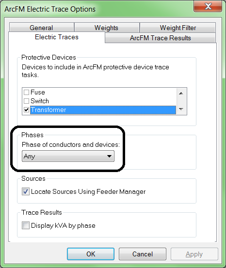
Tip 5: For electric networks only: Set the trace to Any, or choose a phase identical to the phase of your starting feature.
In most cases, setting the trace phase to a different phase than your starting feature will not return any results. For example, running a B phase Downstream trace by starting on an A phase conductor will not succeed. However, there are a few exceptions. For example, running an A phase Downstream trace starting on an ABC conductor will run through the ABC conductor and find any downstream A phase branches. The reverse is not true: running an At Least B upstream trace starting on an A phase conductor will not find the ABC conductors upstream of the starting point.
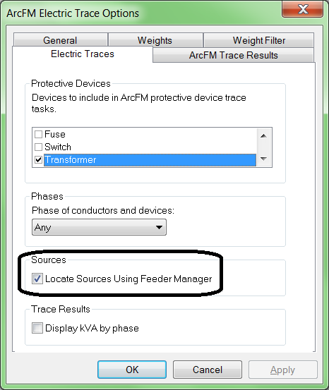
Tip 6: For electric networks only: Verify that Locate Sources Using Feeder Manager is checked.
Given the detailed understanding Feeder Manager has of your network, it only makes sense to use Feeder Manager's list of circuit sources rather than sources which other editors may or may not have manually identified. To access this setting, on the ArcFM Electric Traces toolbar click Options, then display the Electric Traces tab.
Of course, all the tips above will only work if the starting feature for your trace is fully integrated into the network. How can you test a feature to be sure? Find out in the next Tips and Tricks !